Propeller Blade Reverse Engineering
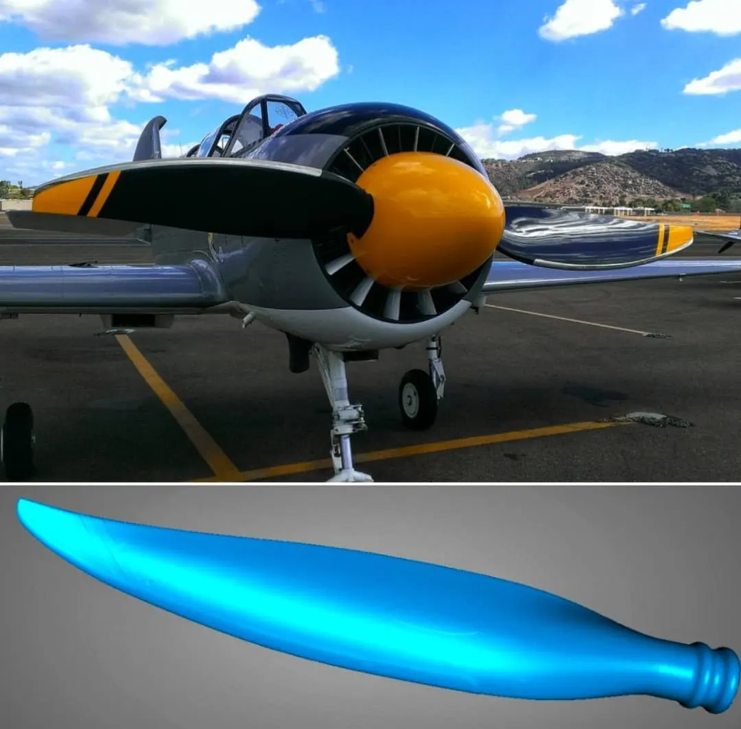
This propeller blade reverse engineering subproject focused on capturing and rebuilding a long aerodynamic surface with continuous curvature and changing thickness. Unlike compact mechanical parts, a propeller blade requires control over the entire profile along its length. Therefore, the main challenge was not only to scan the object, but to preserve its geometric behavior in digital form. This case is part of our reverse engineering projects.
Reconstructing a Continuous Aerodynamic Profile
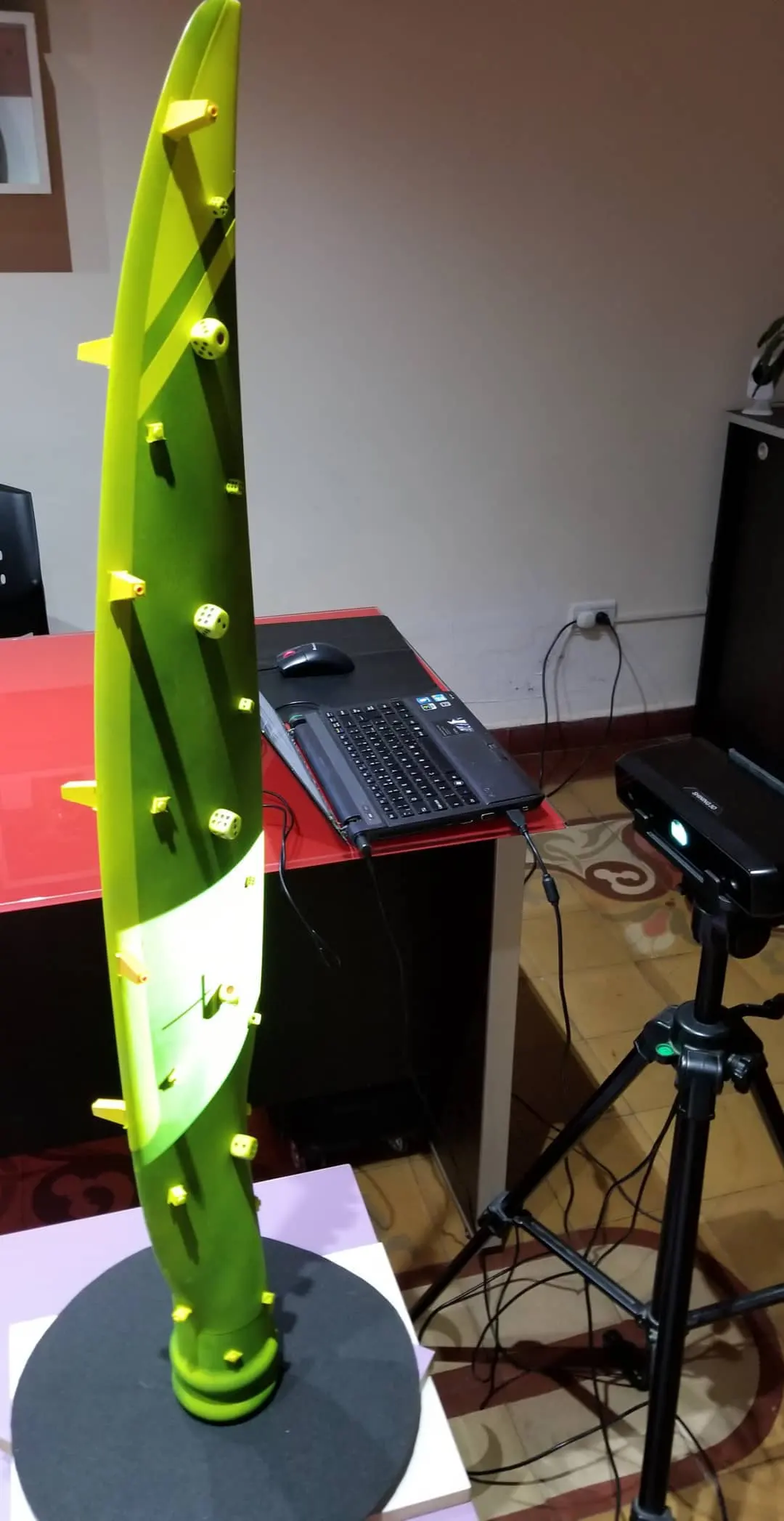
The blade geometry changes along its full length. In addition, the surface transitions must remain smooth and consistent. Because of this, the task required more than standard mesh processing. First, we captured the geometry with multiple aligned scans. Then, we analyzed the surface flow across the blade. As a result, we established a reliable base for reconstruction that preserved the overall aerodynamic logic.
Geometry Characteristics of the Blade
- Long continuous surface with gradual curvature changes.
- Variation in thickness from root to tip.
- Profile twist along the longitudinal axis.
Surface Interpretation Instead of Direct Copy
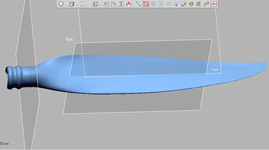
A raw mesh reflects the scanned surface, but it does not always represent a clean engineering shape. Therefore, we interpreted the geometry rather than copying it directly. First, we removed local irregularities from the scan. Then, we rebuilt the blade surface with controlled continuity. As a result, the model became stable, consistent, and suitable for further use.
Why This Step Is Critical
Aerodynamic parts depend on smooth transitions and predictable form. Small surface deviations can affect performance or fit. Therefore, reconstruction must focus on the overall geometry, not just point accuracy. This approach ensures that the digital model behaves as a real component rather than a scanned artifact.
From Digital Model to Physical Blade
After completing the digital model, we produced a physical prototype using 3D printing. This step allowed us to evaluate the reconstructed blade in real scale. In addition, it provided a direct way to inspect proportions, edge transitions, and overall shape. As a result, the workflow connected digital reconstruction with tangible validation.
What Physical Validation Reveals
A printed blade makes geometric relationships easier to understand. For example, it allows comparison between root and tip behavior. Moreover, it helps identify subtle inconsistencies that are difficult to see on screen. Therefore, physical output becomes a key part of the reconstruction process.
Result and Application
The final result was a reconstructed propeller blade model and a full-scale prototype. Together, they provide a clear representation of the original geometry. As a result, the project demonstrates how reverse engineering can be applied to complex aerodynamic components. It also shows how digital and physical workflows can work together in a consistent process. To discuss a similar task, use the contact page.
Project Summary
Object: aircraft propeller blade with extended curved geometry.
Process: scanning, surface interpretation, digital rebuilding, and prototype production.
Result: continuous aerodynamic model and a physical blade prototype for evaluation.
Propeller Blade Reverse Engineering Project FAQ
Why is a propeller blade difficult to reconstruct?
Because the geometry changes along its full length and requires smooth surface transitions. Therefore, simple scanning is not enough.
Does a scan provide a ready-to-use model?
No. A scan captures raw data, but the surface must be interpreted and rebuilt to create a stable engineering model.
Why is surface continuity important?
Because aerodynamic components depend on smooth geometry. Irregularities can affect how the part behaves or fits.
What is the role of 3D printing in this process?
It allows evaluation of the reconstructed blade in physical form, making it easier to assess proportions and surface behavior.